Dam interaction
Soil Compaction Model
The general modelling procedure is based on mass conservation and soil densification. The mass of soil that is displaced by the rock is evenly distributed in the compacted zone and increases its density accordingly. Mass conservation requires that:
$$V_{rock} \ \rho_1 = (V_{plug}-V_{rock}) \ \rho_2$$
where $\rho_1$ is the initial density of the dam material, $\rho_2$
is its compacted (final) density. The amount of material displaced by the rock is:
$$V_{rock} = x \ l^2_{rock}$$
where $x$ is the penetration depth and $l_{rock}$ is the edge length of the cubic rock. This leads to a “plug” volume of:
$$V_{plug} = \frac{x}{3} [ 2 \ l_y \ l_z + l^2_{rock} + \frac{l_{rock}}{2} (2 \ l_y + l_z) ] + \frac{2 \ l_y \ l_z \ l_x}{3}$$
where $l_x,l_y,l_z$ are dimensions of the compacted zone.
$$l_x = s-x, l_y=\frac{l_x}{tan(\beta_h)}, l_z=l_x \ tan(\omega)$$

The equations above combined yield a cubic polynomial for the depth of the compaction front $s$
as a function of the penetration depth $x$. This polynomial equation has three roots (solutions) which can be found analytically. Two of the roots are imaginary and only the real root has physical significance.
Soil resistance model
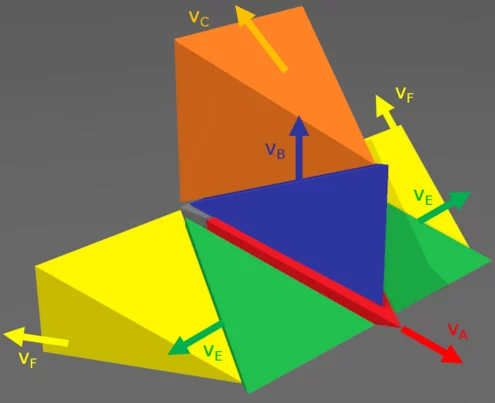
The soil resistance is calculated with an upper bound solution. The approach is based on a bearing capacity problem of a strip foundation. The soil is homogeneous, isotropic, with a Mohr Coulomb plasticity model and associated flow rule $(\Psi=\phi)$.
The rate of work done by external forces $\triangle W_{ext}$ is equal to the rate of energy dissipation $\triangle D_{int}$ in the kinematically admissible velocity field.
$$\triangle W_{ext} = \triangle D_{int}$$
The first source of incremental external work results from the self-weight of the soil prisms
$$\triangle W_{sf} = \sum V_{i} \ \gamma_i \ v_{i,z}$$
where $V_i$ is the volume and $\gamma_i$ is the density of the soil prism and $v_{i,z}$ is the velocity component of the soil body $i$ in the direction of the gravitational force vector.
The second source of incremental external work comes from the surcharge load. For impacts below the dam crest, this surcharge load corresponds to the overburden pressure due to the overlying soil.
$$\triangle W_{sc}=\sum V_{i,sc} \ \gamma_1 \ v_{i,z}$$
where $V_{i,sc}$ is the volume of the overlying soil block of soil prism $i$, $\gamma_1$ is the initial density of the soil material and $v_{i,z}$ is the velocity component of soil prism $i$ in the direction of the gravitational force vector.
The last component of the incremental external work comes from the impact force exerted by the rock on the dam structure.
$$\triangle W_{im} = F_{impact} \ v_0$$
where $F_{impact}$ is the unknown impact force and $v_0=1$ is the virtual unit velocity of the rock.
The only source of incremental internal dissipated energy comes from the cohesion at the discontinuity surfaces between the moving soil bodies.
$$\triangle D = \sum c \ A_{i,j} \ v_{i,j}$$
where $c$ is the cohesion, $A_{i,j}$ is the surface area of the shear plane between soil prism $i$ and $j$ and $v_{i,j}$ is the velocity along the velocity discontinuity between soil bodies $i$ and $j$.
All equations above combined yield the full upper bound solution, where the only unknown is the impact force.
$$F_{impact}=\frac{\triangle D-\triangle W_{sf} – \triangle W_{sc}}{v_0}$$
Implementation in trajectory model
The resulting force $F_{impact}$ for a given time step is applied to the rock by conservation of momentum. Thus, the resulting penetration depths can be calculated after full time integration, when the rock has lost all of its original kinetic energy.
In case of a rebound with a certain conservation of kinetic energy, the rock experiences a discontinuous change of velocity according to hard contact laws. A rebound is initiated as soon as the rock hits a certain predefined maximum penetration depth. This depth is an empirical relation derived by [Gerber, 2019] and is based on the elastic theory of Hertz.
$$d^{max}_\Sigma = 0.16 \ M^{0.25} \ M^{-0.4}_E \ |V^\bot|^{0.8}$$
![Calculation of an upper bound solution for a foundation problem [Soubra, 1999].](https://ramms.ch/wp-content/uploads/csm_foundation_problem_7cc720de57.webp)